Create and use attribute domains
You'll begin this exercise in ArcCatalog, where you'll examine some attribute domains that have been created for a geodatabase and then create some new ones. Next, you'll add fields to a feature class table and apply the new domains to the fields.
The exercise continues in ArcMap, where you'll find out how to use those domains.
Estimated time to complete: 30 minutes
Step 1 Preview a feature class table in ArcCatalog
Start ArcCatalog. Expand your Lab09 folder.
Expand SubdivisionSD.mdb.
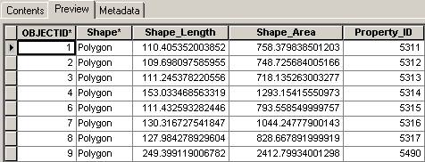
Click the SubdivisionParcels feature class. Preview its table.
Step 1: Preview a feature class table in ArcCatalog
This feature class table contains the default attributes added by ArcCatalog (OBJECTID, Shape, Shape_Length, and Shape_Area). Property_ID is a user-defined attribute.
In the next steps, you will add new fields to this feature class table to store land use and land value attributes and then associate attribute domains with them.
Step 2 Examine geodatabase properties
Right-click SubdivisionSD.mdb and choose Properties.
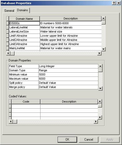
In the Database Properties dialog, click the Domains tab.
Step 2: Examine geodatabase properties.
Notice that some attribute domains have already been created for this geodatabase. The properties for the first domain, ID5000s, are shown in the middle section of the dialog. Because this is a range domain, the Coded Values section at the bottom is blank.
You will be associating this domain with the Property_ID field in the SubdivisionParcels feature class. The other domains will be used in a later exercise.
Step 3 Create a coded value domain
In this step, you will create the first of two new attribute domains using the Database Properties dialog.
![]() Attribute
domains and ArcToolbox™
Attribute
domains and ArcToolbox™
Attribute domains can also be created and assigned using tools in ArcToolbox™ if you have an ArcInfo license.
For more information about using ArcToolbox to create attribute domains, refer to the ArcGIS Desktop Help (Contents tab -> Geoprocessing (including ArcToolbox) -> Geoprocessing tool reference -> Data Management toolbox -> Domains toolset -> An overview of the Domains toolset).
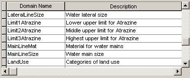
Click in the Domain Name column in the empty row under the last domain and type LandUse.
Press Tab and for Description, type Categories of land use.
Step 3a: Create a coded value domain
Next, you need to specify the properties for the attribute domain.
Make sure the LandUse domain is selected.
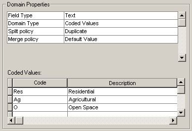
In the Domain Properties area of the dialog, click in the column next to Field Type and choose Text.
Notice that the only domain type for a text field is coded values.
For Split Policy, choose Duplicate.
Next, you need to enter the codes and descriptions for this domain.
In the Coded Values area at the bottom of the dialog, enter the following three codes and descriptions:
|
Code |
Description |
|
Res |
Residential |
|
Ag |
Agricultural |
|
O (uppercase O) |
Open Space |
Step 3b: Create a coded value domain
Keep the Database Properties dialog open. You will continue to work with it in the next step.
Step 4 Create a range domain
In this step, you'll add a range domain for land value.
Click in the Domain Name column in the empty row under the LandUse domain and create another new domain called LandValue.
For its description, enter Land value.
Set the following properties for the LandValue domain:
Field Type: Long
Integer
Domain Type: Range
Minimum value: 10000
Maximum value: 500000
Split policy: Geometry Ratio
Merge policy: Sum Values

Step 4: Create a range domain
Click OK to save the domains and close the Database Properties dialog.
Step 5 Apply a domain to an existing attribute field
Double-click the SubdivisionParcels feature class to open its properties dialog. Click the Fields tab.
Click the gray box to the left of Property_ID to see that field's properties.
In the Field Properties area, click in the column next to Domain.
A dropdown list of all the long integer domains for the geodatabase displays. A domain and the field it is applied to must have the same data type.
Choose ID5000s.
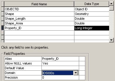
Step 5: Apply a domain to an existing attribute field
Step 6 Add attribute fields and apply domains
In this step, you'll add two new fields to the SubdivisionParcels feature class and, to them, apply the domains you just created.
Click in the first empty row in the Field Name column and enter Land_Use for the new field name.
For Data Type, choose Text.
In the Field Properties area, enter a Default Value of Res.
Click in the column next to Domain and choose LandUse.
LandUse is the only text domain, so it is the only domain displayed in the dropdown list.
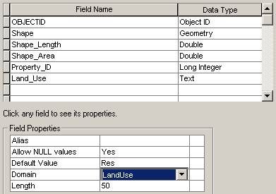
Step 6a: Add attribute fields and apply domains
Now add the second field using the values below.
Field Name: Land_Value
Data Type: Long Integer
Domain: LandValue
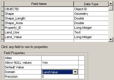
Step 6b: Add attribute fields and apply domains
Click OK.
Step 7 Start ArcMap and add a feature class
To use the domains you've created, you'll edit the features in the SubdivisionParcels feature class.
Start ArcMap with a new empty map.
Drag the SubdivisionParcels feature class into the ArcMap map display area. Close ArcCatalog.
Step 7: Start ArcMap and add a feature class
Step 8 Add attribute values for a parce
Display the Editor toolbar if necessary and start an edit session.
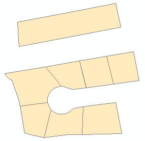
Use the Edit tool ![]() to select the large
parcel to the north of the subdivision.
to select the large
parcel to the north of the subdivision.
Click the Attributes
button ![]() on
the Editor toolbar.
on
the Editor toolbar.
Click in the Value column next to Land_Use and choose Agricultural.
Notice that you see the domain description, not its coded value (Ag).
Click next to Land_Value and enter 250000.
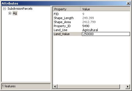
Step 8: Add attribute values for a parcel
Close the Attributes dialog.
Step 9 Split the parcel
You'll use the split policies that you set for the LandUse and LandValue domains to determine how the attributes are handled when you split the agricultural parcel.
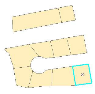
On the Editor toolbar, in the Task dropdown list, choose Cut Polygon Features.
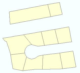
Click the Sketch tool ![]() and draw a line
through the agricultural parcel as shown in the graphic below. Click once to
start the line and double-click to end it.
and draw a line
through the agricultural parcel as shown in the graphic below. Click once to
start the line and double-click to end it.
Now there are two parcels.
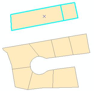
Step 9a: Split the parcel
From the Selection menu, choose Clear Selected Features.
Now you'll examine the attributes for each of the new parcels.
Click the Edit tool and select the parcel on the left. Open the Attributes dialog.
Note: Depending on where you split the original parcel, your values for Shape_Length, Shape_Area, and Land_Value may be different from those shown in the View Result graphic below.
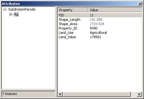
Step 9b: Split the parcel
Select the parcel on the right to see its attributes in the dialog.
![]()
Step 9c: Split the parcel
![]() How were the
values for Property_ID, Land_Use, and Land_Value determined?
How were the
values for Property_ID, Land_Use, and Land_Value determined?
Step 10 Add a residential parcel
In this step, you'll add a parcel to the southeast end of the subdivision.
First, you'll set the snapping environment.
From the Editor menu, choose Snapping. In the Snapping Environment window, click the Vertex option.
When you're adding the new feature, you'll be able to snap to existing parcel vertices.
Close the Snapping Environment window.
Next, from the Editor menu, choose Options. The General tab should be active.
Set the snapping tolerance to 10 map units.
Step 10a: Add a residential parcel
Click OK.
On the Editor toolbar, change the Task to Auto-Complete Polygon.
Using the Sketch tool, draw the three new segments of the polygon as shown below. Double-click to finish the sketch.
The new parcel is added.

Step 10b: Add a residential parcel
Step 11 Enter attribute values
With the new parcel selected, open the Attributes dialog.
Notice that the default value (Residential) has been assigned to the Land_Use attribute.
For Property_ID, enter a Value of 5318. For Land_Value, enter 50000.
Step 11: Enter attribute values
Close the Attributes dialog.
Step 12 Validate the attribute values
Are the values you entered in the previous step valid? For fields that have range domains associated with them, validation is not automatic. You need to run a validation check on the values.
Make sure the new parcel is still selected.
From the Editor menu, choose Validate Features.
Because the Land_Value attribute you added was within the 10,000-500,000 range that you specified when you created the LandValue range domain, you see a message that all the values are valid.
Click OK to close the message.
Step 13 Save your work
From the Editor menu, choose Stop Editing. Click Yes to save your edits.
Save the map document as Development.mxd in your Lab09 folder. You'll work with this map again in the next exercise.
Close ArcMap.
Conclusion
In this exercise, you learned how to create coded value and range domains, associate them with feature class attribute fields, and use the domains during an edit session.
You should be starting to appreciate how attribute domains can help ensure that edits made to data are valid. In the next topic, you'll learn about another feature of the geodatabase that can help prevent errors in your data—subtypes.
Display and query subtypes
In this exercise, you will examine a feature class that contains data for different types of wells that have been tested for the herbicide Atrazine. The well features have been grouped into subtypes.
You'll first examine how the subtypes were set up in ArcCatalog. You'll then add the feature class to ArcMap and see how you can use the subtypes to display and query the data.
Estimated time to complete: 25 minutes
Step 1 Start ArcCatalog and preview an attribute table
Start ArcCatalog. Expand your Lab09 folder.
Expand SubdivisionSD.mdb.
If you did not complete the last exercise, expand the Lab09\Results folder and work with the SubdivisionSD.mdb geodatabase stored there instead.
Expand the Water feature dataset, then click the Wells feature class.
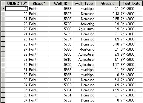
Preview the Wells table.
Step 1: Start ArcCatalog and preview an attribute table
You can see that the Wells feature class contains 19 features and four user-defined attribute fields.
Step 2 Examine the well properties
To view the subtypes associated with the Wells feature class, you will need to access the feature class properties.
In the Catalog tree, double-click the Wells feature class.
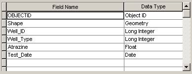
In the Feature Class Properties dialog, click the Fields tab.
Notice that two of the fields, Well_ID and Well_Type, are long integer fields; therefore, either of them could serve as the subtype field.
Step 2: Examine the well properties
Step 3 Examine a subtype
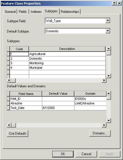
Click the Subtypes tab.
The Well_Type field has been designated as the subtype field. Four subtypes have been created for this feature class. The subtype codes 1-4 will be stored in the database, and the descriptions will display in ArcMap when the data is edited.
Step 3a: Examine a subtype
The default values and domains associated with the first subtype, Agricultural, are currently displayed at the bottom of the dialog, where the other three user-defined attribute fields display.
Notice that the Well_ID field has the ID5000s domain applied to it. This is the same domain you used for parcel IDs in the previous exercise.
The Atrazine field also has a domain associated with it. This domain is used only by the Atrazine field for the Agricultural subtype.
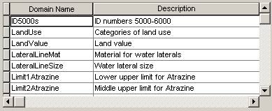
Click the Domains button.
Step 3b: Examine a subtype
The Workspace Domains dialog lists all the domains for the geodatabase.
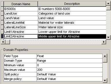
Click the gray box next to the Limit2Atrazine domain to select it.
In the Domain Properties area, you can see that this is a range domain for Atrazine levels between 0 and 200 ppb (parts per billion).

Step 3c: Examine a subtype
Click Cancel to close the Workspace Domains dialog.
Notice that the Test_Date field has no domain, but it does have a default value of 6/1/2000.
Step 4 Examine the remaining subtypes
Click the gray box to the left of subtype code 2 to select the Domestic subtype.
Step 4: Examine the remaining subtypes
Notice that the domain for the Well_ID field is the same as for the Agricultural subtype, but the domain for the Atrazine field is different, as is the default value for the Test_Date field.
Select the other subtypes and examine their properties.
Before you close the Feature Class Properties dialog, you may want to look again at the preview of the attribute table to see how each feature is assigned to a subtype.
Click Cancel to close the dialog.
Step 5 Display the Wells feature class in ArcMap
Start ArcMap and open Development.mxd, the map document you created in the previous exercise, from your Lab09 folder.
If you didn't complete the last exercise, open Development.mxd from the Lab09\Results folder instead.
Step 5a: Display the Wells feature class in ArcMap
Add the Wells feature class to the map, then minimize your ArcCatalog window.
Notice that, in the Table of Contents, the subtypes for the Wells feature class display with their descriptive names.
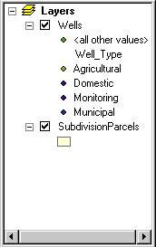
Step 5b: Display the Wells feature class in ArcMap
Click the Full Extent
button ![]() to
see all the wells.
to
see all the wells.
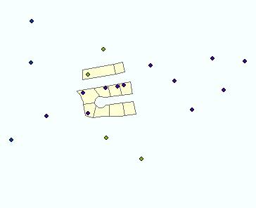
Step 5c: Display the Wells feature class in ArcMap
If you like, change the symbology for the subtypes to make them easier to distinguish.
Step 6 Query domestic wells
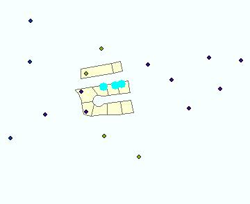
In this step, you want to find all the domestic wells with Atrazine levels that equal or exceed the national drinking water health limit of 3 parts per billion (ppb).
From the Selection menu, choose Select By Attributes.
In the Select By Attributes dialog, Wells should be the selected layer. Make sure the Method is Create a new selection.
Build the following query statement:
[Well_Type] = 2 AND [Atrazine] >= 3
![]()
Step 6a: Query domestic wells
Click Apply and close the dialog.
Three domestic wells exceed the limit. You'll use this information in the next exercise.
Step 6b: Query domestic wells
Step 7 Save your work
Make sure the three well features are still selected.
Save your changes to the map document. If you're continuing to the next exercise at this time, close ArcMap but leave ArcCatalog running.
If you're not continuing at this time, close both ArcMap and ArcCatalog.
Conclusion
In this exercise, you examined another feature class in the SubdivisionSD.mdb geodatabase. You saw how four subtypes had been set up and associated with attribute domains.
A subtype can have a domain and a default value associated with each user-defined attribute field. Features are grouped into subtypes based on the values in the subtype field in the attribute table. When a layer with subtypes is displayed in ArcMap, you can query the subtypes as you would any other attribute.
In the next exercise, you'll learn how to create subtypes in ArcCatalog and then use the subtypes to edit data in ArcMap.
Create and edit subtypes (ArcEditor, ArcInfo users only)
To complete this exercise, you must have an ArcEditor or ArcInfo license. In other word, you can do this only in the Geography labs HN1090 or at your work space if you happen to have an employer who has an ArcEditor or ArcInfo license. The student versions of ArcView won’t work, nor the CD in the back of the Getting to Know ArcGIS book.
Now that you've seen how subtypes are set up, you'll create some yourself. You'll use those subtypes to add features and attribute data in ArcMap.
You'll work with the map document and the data from the previous exercise and add water lines to the parcels that contain contaminated wells.
Estimated time to complete: 30 minutes
Step 1 Start ArcCatalog and preview the Lines attribute table
Start or restore ArcCatalog.
In the Catalog tree, expand your Lab09 folder.
Expand the SubdivisionSD.mdb geodatabase.
Note: If you worked with the geodatabase and map document stored in the Results folder in the previous exercise OR if you didn't save the Development.mxd map document in the previous exercise, navigate to Results\Subdivision.mdb instead.
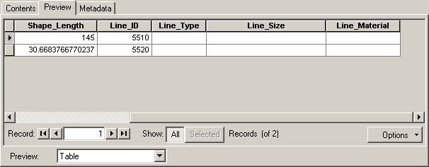
Expand the Water feature dataset and preview the table for the Lines feature class.
The table contains one user-defined attribute field, Line_ID.
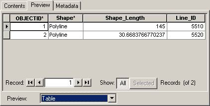
Step 1: Start ArcCatalog and preview the Lines attribute table
Step 2 Add attribute fields
In this step, you'll add three new attribute fields to the Lines feature class.
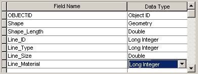
Double-click the Lines feature class to open its properties dialog. Click the Fields tab.
To add new fields, you click an empty row in the Field Name column and type in the new field name. You then click in the Data Type column and choose the appropriate data type from the dropdown list.
Add the following fields:
|
Field Name |
Data Type |
|
Line_Type |
Long Integer |
|
Line_Size |
Double |
|
Line_Material |
Long Integer |
Step 2a: Add attribute fields
Click OK.
In the feature class table, you see the fields you just added. The Line_Type field will contain the subtype designations.
Step 2b: Add attribute fields
Step 3 Add subtypes for the water lines
In this step, you'll create two subtypes for the Lines feature class. The features in this feature class will either be mains or laterals.
Double-click the Lines feature class to reopen the Feature Class Properties dialog. Click the Subtypes tab.
In the Subtype Field dropdown list, choose Line_Type.
Only the integer fields appear in the list because other field types cannot be used as a subtype field.
Next, you'll add the codes and descriptions for the subtypes.
Click in the first cell under Code and replace the value with 1.
Press Tab and enter Main for the Description.
Create another subtype with a code of 2 and a description of Lateral.
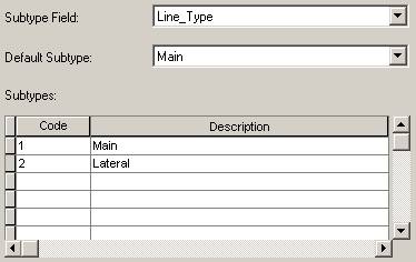
Step 3: Add subtypes for the water lines
Step 4 Examine attribute domains
In the next steps, you'll finish creating the two subtypes by assigning default values and domains. To save time, the domains have been created for you.
Click the Domains button.
The dialog shows all the domains that have been created for the SubdivisionSD geodatabase.
The ID5000s domain will be used to specify valid ID values for both subtypes. LateralLineMat and LateralLineSize will be used for the Lateral subtype. MainLineMat and MainLineSize will be used for the Main subtype.
Click the gray box to the left of each domain name to see its properties.
When you're finished, click Cancel to close the Workspace Domains dialog.
Step 5 Specify default values and domains for water mains
In the Subtypes list, click the gray box to the left of Code 1 to select the Main subtype.
You'll enter default values and domains for water mains at the bottom of the dialog.
For the Line_ID field, click in the Domain column and choose ID5000s from the dropdown list.
For Line_Size, click in the Default Value column and type 10. In the Domain column, choose MainLineSize.
MainLineSize is a range domain which specifies that values from 10 to 16 are valid.
For Line_Material, enter 2 for the Default Value and choose MainLineMat for the Domain.
MainLineMat is a coded value domain. A default value of 2 specifies copper.
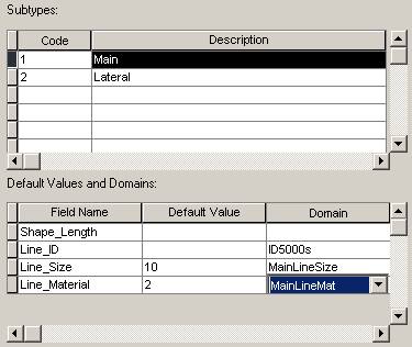
Step 5: Specify default values and domains for water mains
Step 6 Specify default values and domains for water laterals
Now you'll enter the default values and domains for the second subtype, Lateral.
In the Subtypes list, select Code 2 and enter the following default values and domains for laterals:
|
Field Name |
Default Value |
Domain |
|
Line_ID |
|
ID5000s |
|
Line_Size |
2 |
LateralLineSize |
|
Line_Material |
4 |
LateralLineMat |
LateralLineSize is a range domain which specifies that values from 2 to 6 are valid. LateralLineMat is a coded value domain. A default value of 4 specifies plastic.
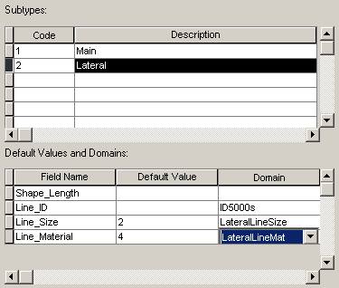
Step 6: Specify default values and domains for water laterals
Step 7 Specify a default subtype
Because you will usually add more laterals than mains, you will make laterals the default.
In the Default Subtype dropdown list at the top of the dialog, choose Lateral.
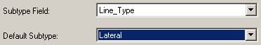
Step 7: Specify a default subtype
Click OK.
You have now created two subtypes for the Lines feature class. Next, you will see how subtypes help make editing data faster and more accurate.
Step 8 Start ArcMap and add the Lines feature class
Start ArcMap and open the Development.mxd map document you worked with in the previous exercise.
Note: If you did not complete the previous exercise, open Development2.mxd from the Lab09\Results folder instead.
Three domestic wells should be selected.
Step 8a: Start ArcMap and add the Lines feature class
Add the Lines feature class, then close ArcCatalog.
Notice in the Table of Contents that the subtypes for the Lines feature class display with their descriptive names.
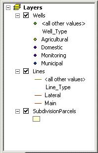
Step 8b: Start ArcMap and add the Lines feature class.
Step 9 Start an edit session
In the upcoming steps, you are going to edit the water lines. First, of course, you need to start an edit session.
Display the Editor toolbar, if necessary. From the Editor menu, choose Start Editing.
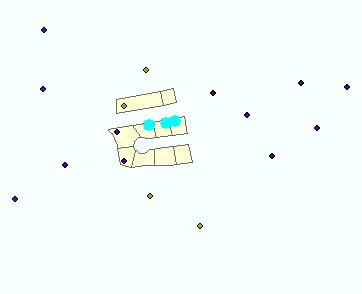
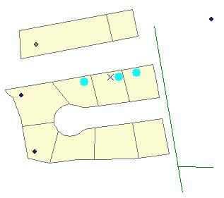
Zoom in on the parcels and water lines.
Step 9: Start an edit session
Notice the three parcels with the selected wells. You selected these wells in the previous exercise because they contained a level of Atrazine (an herbicide) that equaled or exceeded the national drinking water health limit.
In step 12, you'll add water lines to these three parcels.
Step 10 Specify subtypes for the existing water lines
The Lines feature class already contained two features when you created the subtypes for the feature class. You'll need to apply a subtype to each of the features.
Click the Edit tool ![]() and select the
longer line feature.
and select the
longer line feature.
Click the Attributes
button ![]() on
the Editor toolbar.
on
the Editor toolbar.
Click in the Value column next to Line_Type and choose Main.
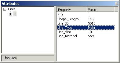
Step 10a: Specify subtypes for the existing water lines
Notice that as soon as you chose a subtype, the Line_Size and Line_Material default values displayed in the Attributes dialog. Note also that you see the descriptions for the subtype and the attribute with the coded value domain.
Next, select the shorter line feature.
In the Attributes dialog, choose Lateral as the Line_Type.
For this feature, the subtype's default values are not appropriate.
Change the Line_Size to 8 and the Line_Material to Copper.
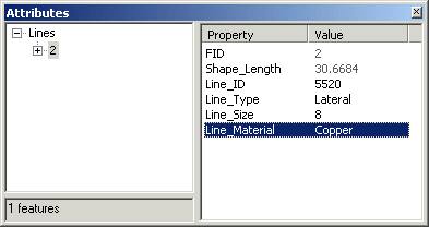
Step 10b: Specify subtypes for the existing water lines
Close the Attributes dialog.
If you like, change the symbology for the Main and Lateral subtypes to make them easier to distinguish.
Step 11 Set the snapping environment
You're going to add some new features to the Lines feature class, but before you do this, you need to set up the snapping environment.
From the Editor menu, choose Snapping.
In the Snapping Environment dialog, check the box under Edge for the Lines layer. If any other boxes are checked, uncheck them.
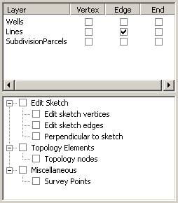
Step 11: Set the snapping environment
Close the Snapping Environment window.
From the Editor menu, choose Options.
In the General tab, set the snapping tolerance to 10 map units, then click OK.
Step 12 Add new water lines
You'll add a water main and three laterals to the parcels with the contaminated wells.
On the Editor toolbar, the Task should be set to Create New Feature.
In the Target dropdown list, expand Lines to see its subtypes, then choose Main.
![]()
Step 12a: Add new water lines
The new feature you create will have the Main subtype applied to it.
Click the Sketch tool ![]() .
.
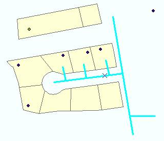
Using the graphic below as a guide, add a main that starts from the existing water main and extends into the middle of the subdivision cul-de-sac. Click once to start the line and double-click to end the line.
Now you'll add three laterals that extend from the new water main about a third of the way into the three parcels with the contaminated wells.
On the Editor toolbar, change the Target to Lines: Lateral.
Using the Sketch tool, draw the three new laterals.
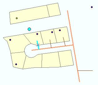
Step 12b: Add new water lines
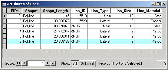
Step 13 Add attribute values
The easiest way to see the attributes for all the water line features is to open the attribute table.
In the Table of Contents, right-click Lines and choose Open Attribute Table.
Notice that the default values for each subtype have been added for all the new features. You did not specify a default value for Line_ID, so you'll need to add the values.
Step 13a: Add attribute values
Note: Your Shape_Length values may be different than those shown in the View Result graphic above.
Click in the Line_ID cell for the water main you added and enter 5530. Click in the cell beneath.
For the three new lateral lines, add Line_ID values of 5540, 5550, and 5560.
Step 13b: Add attribute values
Close the attribute table.
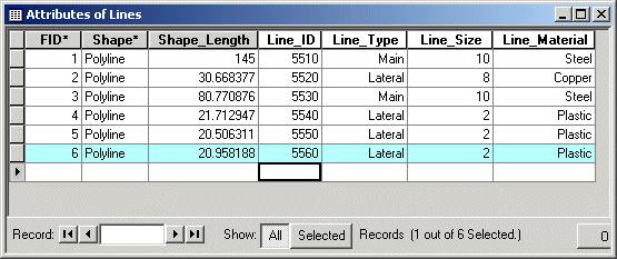
Step 14 Validate the attribute values
When you created the subtypes, recall that you applied attribute domains to three of the attribute fields. You'll use those domains to validate the attribute values for all the water line features.
Right-click Lines, choose Selection, then click Select All.
Step 14a: Validate the attribute values
From the Editor menu, choose Validate Features.
You see a message that one of the lines contains an invalid attribute value. The feature is selected on the map and the validation message tells you what the error is.
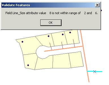
Step 14b: Validate the attribute values
Click OK to close the message.
Open the Attributes dialog for the selected feature. Change the Line_Size value to 4.
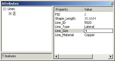
Step 14c: Validate the attribute values
Close the dialog. From the Editor menu, choose Validate Features again.
This time, the attributes for the feature are valid.
Click OK to close the validation message.
Step 15 Save your work
From the Editor menu, choose Stop Editing and save your edits.
Save the map document as well, then close ArcMap.
Conclusion
You've now had some practice creating subtypes for a feature class and have seen how subtypes can help prevent errors when editing data. For example, when you added the Lines feature class to the map document, the default values and attribute domains associated with the subtypes made data entry faster and more accurate.
In the next topic, you will explore a third type of behavior that can be added to a geodatabase—relationships.
Work with relationships
Efficient database design often calls for storing spatial data in one table and attribute data in another table. Such is the case with the data in this exercise. The data has been imported into a geodatabase as a feature class and a nonspatial table.
By themselves, neither is particularly useful. However, a relationship class for the two objects has been set up so that the attribute data can be queried and the query results can be displayed on the map.
Estimated time to complete: 20 minutes
Step 1 Start ArcMap and add data
Start ArcMap and open a new empty map.
Add the BlockGroups feature class from the Lab09\Wilson.mdb geodatabase.
You see a map of 1990 U.S. census geography (block groups).
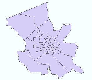
Step 1: Start ArcMap and add data
Step 2 Open a related table
The BlockGroups feature class participates in a relationship class with a table that stores demographic data collected in the 1990 U.S. census.
You can access the related table through the BlockGroups table.
Open the BlockGroups attribute table.
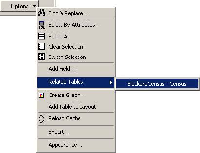
At the bottom of the table window, click the Options button and choose Related Tables.
Tip: If you don't see the Options button, make the table wider.
The name of the relationship class and the related table display.
Step 2a: Open a related table
Click the relationship label to open the Census table.
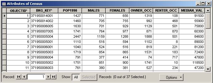
Step 2b: Open a related table
The Census table contains population and housing data from the 1990 U.S. census.
Step 3 Query related records
With both tables open, you can query records in one table and the related records in the other table will be selected as well. You'll query the Census table to find block groups where there are more renters than owners.
In the Attributes of Census table, click Options, then click Select By Attributes.
In the Select By Attributes dialog, build a query to select all the records where there are more renter-occupied (RENTER_OCC) than owner-occupied (OWNER_OCC) housing units.
![]()
Step 3a: Query related records
Click Verify to make sure your expression is valid, then click OK to close the message.
Click Apply, then close the Select By Attributes dialog.
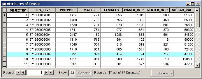
Step 3b: Query related records
Records are selected in the Attributes of Census table. To see the selected records in the Block Groups table (and the selected features on the map), you need to refresh the table display.
In the Attributes of Census table, click the Options button and choose Related Tables.
This time, BlockGroups is the related table.
Click the relationship label to refresh the table and update the map display.
Move the tables out of the way if necessary and examine the map.
Block groups where there are more renters than owners are now selected.
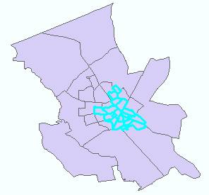
Step 3c: Query related records
![]() What is the
cardinality for this relationship class?
What is the
cardinality for this relationship class?
Hint: Look at the number of selected records in each table.
Before proceeding, clear the selected records in both tables (in each table, click the Options button, then choose Clear Selection).
Close the tables.
Step 4 Join the tables
In ArcMap, before you can symbolize or label features based on attributes from a related table, you must join the tables using the relationship. In this step, therefore, you'll create a join.
Open the Layer Properties dialog for BlockGroups. Click the Joins & Relates tab.
In the Joins area, click Add.
The Join Data dialog displays.
In the dropdown list under "What do you want to join to this layer," choose "Join data based on a pre-defined relationship class."
Under "Choose the relationship class to base the join on," Census should be selected.
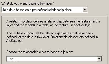
Step 4: Join the tables
Click OK.
Census is now listed in the Joins area.
Click Apply in the Layer Properties dialog.
Keep the Layer Properties dialog open; you will continue to work with it in the next step.
Step 5 Symbolize features based on attributes from the related table
Now that you have joined the tables, you can symbolize the block groups based on attributes in the Census table.
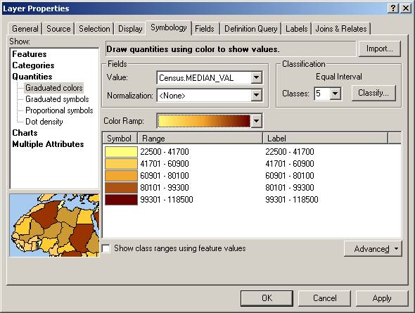
Click the Symbology tab.
In the Show area on the left, click Quantities.
Graduated colors should be selected.
In the Field Value dropdown list, choose Census.MEDIAN_VAL.
Note that the joined field name displays as table name.field name.
Click Classify and choose Equal Interval in the Classification Method dropdown list. Click OK to close the Classification dialog.
Step 5a: Symbolize features based on attributes from the related table
Click OK to apply the new symbology and close the dialog.
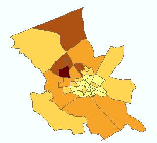
Step 5b: Symbolize features based on attributes from the related table
The block groups are now symbolized based on their median value, which is stored in a field in the Census table. You could also label the block groups using this or any other field in the Census table.
Step 6 Examine relationship class properties
Now that you've been introduced to how a relationship functions in ArcMap, you'll examine how it was set up in ArcCatalog.
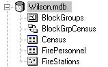
Start ArcCatalog and expand the Lab09\Wilson.mdb geodatabase.
Minimize your ArcMap window.
Click the BlockGrpCensus relationship class.
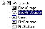
Step 6a: Examine relationship class properties
Click the Preview tab.
Unlike a feature class, you cannot preview a relationship class. You can, however, view the properties for a relationship class and the properties of its related tables and feature classes.
Double-click BlockGrpCensus.
In the Relationship Class Properties dialog, click the General tab.
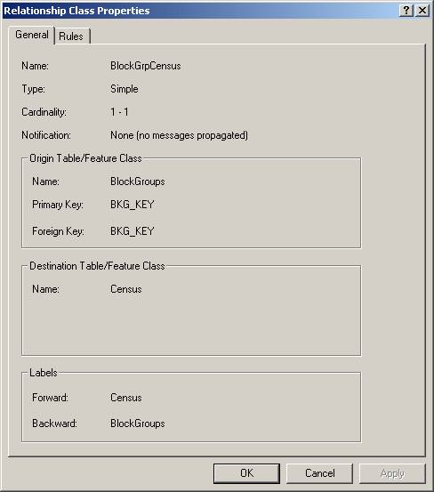
Step 6b: Examine relationship class properties
Here you see how the feature class and table you worked with in ArcMap are related. For example, you can see that the key field in both the origin and destination table is named BKG_KEY.
How can you determine the field type for the key fields?
Click the Rules tab.
No rules have been created for this relationship class.

Step 6c: Examine relationship class properties
Close the dialog.
Step 7 Examine feature class properties
Double-click the BlockGroups feature class to open its properties dialog. Click the Relationships tab.
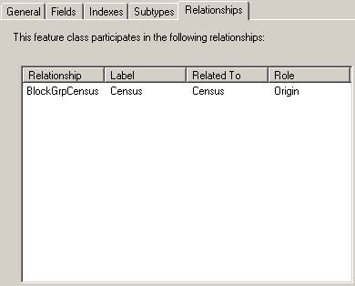
Step 7: Examine feature class properties
You see a list of the relationships that BlockGroups participates in. In this case, there is only one. Similar information is provided in the Census table properties.
![]() What is the
field type of the key field on which the relationship is based?
What is the
field type of the key field on which the relationship is based?
Remember that the key field is named BKG_KEY. To find the field type, click the Fields tab and look at the Data Type for this field.
Close the Feature Class Properties dialog.
Step 8 Save your work
If you're continuing to the next exercise at this time, leave ArcCatalog open. Otherwise, close ArcCatalog.
Restore ArcMap and save your map document as WilsonCensus.mxd in your Lab09 folder.
Close ArcMap.
Conclusion
In this exercise, you learned how to use related tables to query and symbolize data in ArcMap. You used ArcCatalog to examine the properties of the related tables.
You saw how the relationship between the BlockGroups feature class and the Census table was stored as an object in the geodatabase. If you have ArcEditor or ArcInfo, you will learn in the next exercise how to create a relationship class and use it to update the data in the related tables.
Create and edit relationships (ArcEditor, ArcInfo users only)
To complete this exercise, you must have an ArcEditor or ArcInfo license.
In this exercise, you will again work with data stored in the Wilson geodatabase. This time, the data is for the city's fire stations and their personnel. The fire station data is contained in a feature class. The personnel data is contained in a nonspatial table.
You'll create a new relationship class for the two tables and assign a relationship rule. You'll then edit the related data in ArcMap, adding and removing records from the relationship.
Estimated time to complete: 40 minutes
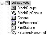
Step 1 Start ArcCatalog
Start or restore ArcCatalog. Under your Lab09 folder, expand the Wilson.mdb geodatabase.
You will create a relationship class in this geodatabase to relate the stations in the FireStations feature class to the employee data stored in the FirePersonnel table.
Step 1: Start ArcCatalog
Step 2 Determine relationship class properties
Before you create a relationship class, you need to decide what its properties will be. Remember, once you have created a relationship class, you cannot modify its properties—you can only delete it and start over.
The relationship properties you need to specify are:
- Relationship class name
- Origin table and destination table
- Type of relationship (simple or composite)
- Forward and backward labels for navigation between the tables
- Cardinality
- Relationship attributes
- Primary and foreign key fields
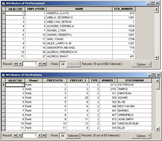
Preview the tables for FireStations and FirePersonnel.
Using what you learned in the previous exercise, see how many of the properties listed above you can determine and write them down.
Step 3 Create the relationship class
In this step, you will create a relationship class to model the relationship between fire stations and fire personnel.
Right-click Wilson.mdb, choose New, then click Relationship Class.
The New Relationship Class wizard opens.
In the first panel, you need to name the relationship class and specify the origin and destination tables.
The relationship class name should uniquely identify it and reflect which tables participate.
Enter FStationsPersonnel for the relationship class name.
Under Origin table/feature class, click FireStations.
Under Destination table/feature class, click FirePersonnel.
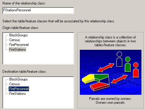
Step 3a: Create the relationship class
Click Next.
Now you need to select the type of relationship.
Employees exist independently of fire stations. For example, if a fire station is closed down and removed from the feature class of active stations, the employees will be shifted to other stations. You do not want employee records deleted if a fire station is deleted, so the relationship will be simple.
Accept the default of a "Simple (peer to peer) relationship" and click Next.
The defaults for labels and messages are appropriate for the relationship you are creating.
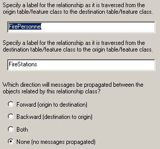
Step 3b: Create the relationship class
Click Next.
In the fourth panel, you specify the cardinality for the relationship. Each fire station has more than one employee.
Select 1-M (one to many) as the cardinality.
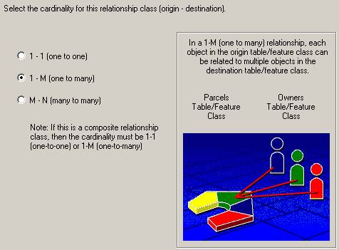
Step 3c: Create the relationship class
Click Next.
In the fifth panel, you will accept the default option of "No, I do not want to add attributes to this relationship class."
Click Next.
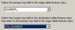
Now you must select the key fields for the origin and destination tables. Both tables have a field that stores the fire station number.
In the feature class table (origin table), the field is named NUMBER_. In the FirePersonnel table (destination table), the field is named STA_NUMBER.
For the primary key, choose NUMBER_.
For the foreign key, choose STA_NUMBER.
Step 3d: Create the relationship class
Click Next.
The final panel summarizes the information you entered in the previous panels.
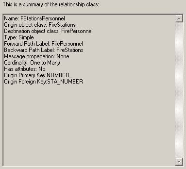
Step 3e: Create the relationship class
Check to make sure the information is correct, then click Finish.
The new relationship class displays in the Catalog tree.
Step 3f: Create the relationship class
Step 4 Add a relationship rule
Now that you have created a relationship class, you can add rules to it.
The city of Wilson requires that at least five, but no more than 20, employees be stationed at each fire station. To enforce this restraint when users edit the database, you will create a relationship rule.
Make sure that ArcMap is closed. ArcCatalog will not allow you to set rules for a relationship class while you're viewing data from the same personal geodatabase in ArcMap.
Double-click the FStationsPersonnel relationship class.
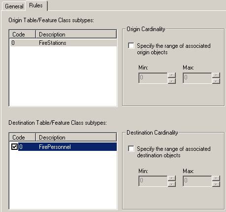
In the Relationship Class Properties dialog, click the Rules tab.
Under Origin Table/Feature Class subtypes, click FireStations.
This activates the Destination Table box.
Under Destination Table/Feature Class subtypes, click FirePersonnel.
Check the box under Code.
Now the cardinality options are enabled.
Step 4a: Add a relationship rule
Because the FStationsPersonnel relationship is one-to-many, your rule will specify a range for the destination cardinality.
Check the box under Destination Cardinality.
To prevent you from inputting a maximum value that is lower than the minimum value, ArcCatalog requires that you enter the maximum value first.
For Max, enter 20.
For Min, enter 5.
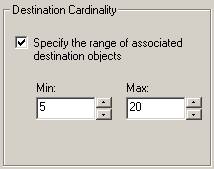
Step 4b: Add a relationship rule
Click OK.
The relationship class now has a rule that says there must be between five and 20 employees per station.
Step 5 Start ArcMap and verify the table relationship
Start ArcMap with a new empty map. Add the FireStations feature class.
Close ArcCatalog.
Verify that the relationship was created correctly by opening the related table, FirePersonnel.
![]() How
do I open the related table?
How
do I open the related table?
In the last exercise, you learned how to access related tables in ArcMap. Use the same process for this step:
1. Open the FireStations attribute table.
2. Click Options, choose Related Tables, then click FStationsPersonnel:FirePersonnel to open that table.
Arrange your windows so that you can see both tables.
Step 5: Start ArcMap and verify the table relationship
Step 6 Verify related records
To verify that the records are correctly related, you'll create a query to select employees who work in the West Nash station.
In the Attributes of FireStations table, click Options, then choose Select By Attributes.
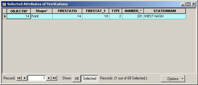
In the dialog, build a query to select the record whose STATIONNAM attribute is WEST NASH.
![]()
Step 6a: Verify related records
Click Verify, then close the verification message.
Click Apply and close the Select By Attributes dialog.
The West Nash record is selected in the table and the feature is selected on the map.
At the bottom of the FireStations table, click Show Selected to see only the selected record.
Step 6b: Verify related records
There are no selected records in the FirePersonnel table because you haven't refreshed its display yet.
In the Attributes of FireStations table, click Options and choose Related Tables, then click FStationsPersonnel:FirePersonnel.
To see the selected employee records, click Show Selected in the FirePersonnel table.
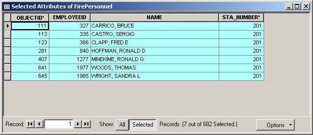
Step 6c: Verify related records
Seven employees records are associated with station number 201, the number of the West Nash station. If the relationship had been incorrectly defined with one-to-one cardinality, only the first employee, Bruce Carrico, would have been selected in the FirePersonnel table.
Note: If the Selected Attributes of FirePersonnel table opens as a new table on top of the first table after you click the Selected button, close the Attributes of FirePersonnel table in which 0 records are selected.
Step 7 Select related records
In the next steps, you will learn how to edit records while maintaining the integrity of the relationship.
Scott Glaze, an employee at the Washington station, has gone on extended leave. Therefore, you need to remove him from the relationship with the station while maintaining his employee record. First, you'll select his personnel record and the station where he works.
In the FirePersonnel table, click Show All to see all the table records again.
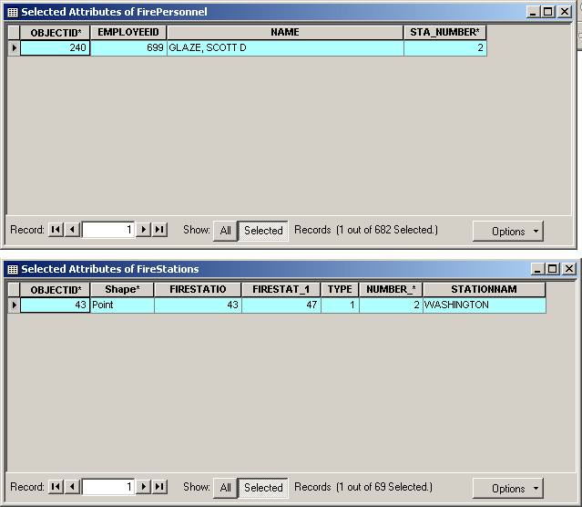
Use the Select By Attributes dialog to select Scott Glaze's record.
![]()
Step 7a: Select related records
Click Show Selected to show the selected record.
Refresh the display of the FireStations table. (In the FirePersonnel table, click Options and choose Related Tables, then click FStationsPersonnel:FireStations).
Step 7b: Select related records
Step 8 Remove a record from the relationship
You'll need to start an edit session to remove Scott Glaze from the relationship.
From the Editor menu, choose Start Editing.
In the FirePersonnel table, delete the station number value (2) from Scott Glaze's record, then click in the cell beneath so that his record is updated.
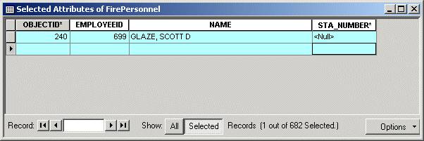
Step 8: Remove a record from the relationship
Now you'll check to see that there are still enough employees at the Washington station.
From the Editor menu, choose Validate Features.
The Validate Features command checks your edit against any rules you have set to determine if the edit was valid.
Your edit is valid because there are still five employees at the Washington station. In the FireStations table, the record for Washington station is unselected. You no longer see it because you are currently showing only selected records.
Reminder: When you validate features, only records with invalid attributes are selected.
Click OK to close the validation message.
Refresh the FirePersonnel table (using the Options menu in the FireStations table) and click All to show all records.
Step 9 Add records to the relationship
Two new employees have joined the fire department and the Prince William station has requested that they be assigned to it.
Display all the records for the FireStations table. Use Select By Attributes to select the Prince William station. Note its location on the map.
The Prince William station is located in a high fire area, so you'll honor the station's request and add the two employees.
Refresh the FirePersonnel table.
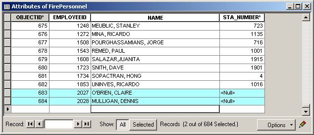
Scroll to the bottom of the FirePersonnel table. In the blank row, enter 2027 for EMPLOYEEID and O'BRIEN, CLAIRE for NAME.
Repeat the process for MULLIGAN, DENNIS, employee ID 2028.
Notice that the OBJECTID values are added automatically when you click outside the records.
Select both records by holding down the Ctrl key and clicking the gray boxes to the left of each.
Step 9: Add records to the relationship
Step 10 Update attributes
Now that you've added the records, you can use the Attributes dialog to automatically add the station number to both records.
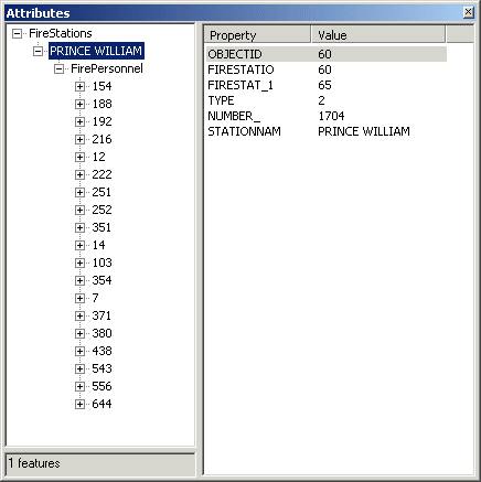
On the Editor toolbar, click the Attributes button.
On the left side of the Attributes dialog, expand PRINCE WILLIAM to see the relationship label.
Expand FirePersonnel to see the related attributes.
Step 10a: Update attributes
Note: Your FirePersonnel numbers may be listed in a different order than that shown in the graphic.
Right-click the FirePersonnel relationship label and click Add Selected.
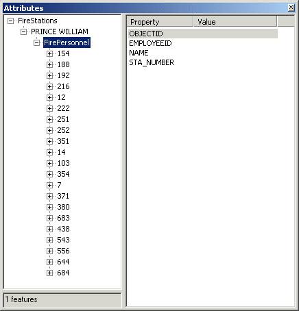
Step 10b: Update attributes
The two employees are added to the relationship.
Now validate the edit.
From the Editor menu, choose Validate Features.
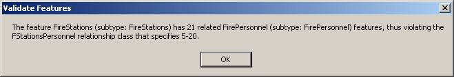
Step 10c: Update attributes
The edit put you over the limit for the number of employees allowed for a station.
Note: The FireStations feature class has no subtypes, so the feature class name is given in parentheses instead.
Click OK to close the validation message.
In the FirePersonnel table, notice that the records for both new employees have been updated with the station number.
Step 11 Modify a relationship
To keep within the city guidelines, you'll transfer Dennis Mulligan. (If you choose to do the Challenge, Dennis will be transferred to the Carter station.)
In the Attributes dialog, right-click the record for Dennis (684) and click Remove From Relationship.

Step 11: Modify a relationship
Close the Attributes dialog, then validate the edit.
All features should now be valid. Close the validation message.
Notice that, in the FirePersonnel table, Dennis's record now has no station number.
Step 12 Save your work
From the Editor menu, choose Save Edits.
Save the map document as WilsonFire.mxd in your Lab09 folder.
If you want to do the Challenge, go there now. Otherwise, close ArcMap.
![]() Challenge: Transfer Dennis to Carter station
Challenge: Transfer Dennis to Carter station
Using what you learned in steps 9-11, add Dennis Mulligan to the Carter station.
Conclusion
This exercise focused on creating a relationship class and using it to query and edit data. You first created a relationship between the fire stations and the fire personnel. You then set up a relationship rule to control the number of employees per station, and, finally, you used that rule to validate edits in ArcMap.
The relationship class allowed you to identify and fix an invalid edit. Along with attribute domains and subtypes, relationship classes add value to a geodatabase—endowing your data with these behaviors can help you keep your geodatabase accurate and up-to-date as features in the real world change.
Review questions
1. Is it possible to apply multiple attribute domains to a single field?
2. Can you create a relationship between a feature class in one geodatabase with a nonspatial table in a different geodatabase?
3. You have a feature class containing oil pipelines and a nonspatial table containing maintenance records for the pipelines. You want to relate the two tables. Which table is the origin table and which is the destination table?